Wind Turbine Aerodynamics - 6 - Computational Fluid Dynamics
19 August 2026, Pascal Weihing
Introduction
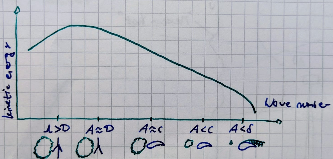
actuator disk model ACD used to model general flow behaviour without any high resolution details gusts smaller than the airfoil have strong influence on boundary layer development, deparation, inflow noise - more advanced simulations are required
| Change of | Velocity deficit | $U_\infty, \alpha$ | $\alpha, c_p$ | $c_p, Tu$ | $Tu$ |
|---|---|---|---|---|---|
| Effect on | wake dynamics | unsteady loads | Load spectra, separation, low freq. noise | BL development, separation, inflow noise | Transition, separation, TE noise |
| Numerical methods | ACL, ACD + LES | URANS | URANS, DES | DES, WMLES, LES | LES, DNS |
CFD Codes Used in the European Wind Energy
- FLOWer
- developed at IAG, DLR
- block-structured code
- compressible
- moving meshes
- overset mesh technique
- actuator disc model
- actuator line model
- TAU
- developed at DLR
- unstructured
- compressible
- moving meshes
- overset mesh technique
- actuator disc model
- OpenFOAM
- open source
- unstructured
- in / compressible
- moving meshes
- sliding mesh technique
- actuator disc model
- actuator line model
- EllipSis3D
- developed at DTU
- block-structured code
- incompressible
- moving meshes
- pverset mesh technique
- actuator disc model
- actuator line model
Governing Equations
Computational Fluid Dynamics solves the Navier Stokes equations using numerical algorithms
Conservation Laws
mass, momentum, energy. total variation in a control volume can be expressed as net effect of:
- transport of a property across boundary (flux)
- internal forces (sources)
- external forces acting on the volume (pressure, shear stress, ...)
Geometrically Resolved Simulations
Actual surface boundaries of components are taken into account during simulations
- aerodynamic effects are captured without need for engineering models (unsteady aerodynamics, dynamic stall, rotational augmentation)
- interaction phenomena between different turbine components are captured
- investigation on many physical problems (loads, flow separation, ...) are possible
- time consuming meshing and grid assembly
- many parameters, results may differ between users
- boundary layer cells need to be resolved - typical wind turbine simulation circa 50M - 100M cells - significant computational cost
- sometimes more difficult to achieve convergence
Relative Grid Motions
- requirement: grid motions or deformations in a uniform low must not introduce any velocities
- besides the conservation of mass, momentum and energy, the so-called geometric conservation law GCL must be satisfied in case of deforming meshes
- sum of entire motion of the control volume's boundary must be reflected in a change on the volume
- the GCL must be discretized and solved with the same numerical scheme as the main equations
Overset Grid Technique
Different grids for different components, which are meshed seperately. The meshes overlap, which can be accounted for by the solver: For each component a motion is specified. At the mesh boundaries where grids overlap, the two flow solutions are interpolated. Holes are defined which carry a motion as well and cut out the cells from the component grid.
Actuator Disc Method ADM
- almost no effort in creating the meshes
- only few imput parameters needed, especially for uniformly loaded disc
- saves grid points compared to blade resolved simulations
- time step can be adapted to atmospheric velocity scales
- can be easily implemented into other code bases (meteorological, ...)
- saving computational time, ideal to assess wind farms!
- inaccuracies in the near wake
- not suited to study the detailed physics of wake breaktdown
- transition from near wake to far wake might be inaccurate
- not suited to study the aerodynamics of the rotor
Effect of the rotor is modeled by a momentum source term $Q_v$ being injected over the rotor disc
$$ \frac{\partial}{\partial t} \int_\Omega W d\Omega + \int_{\partial \Omega} (F_C - F_D) \cdot dS = \int_\Omega Q_v d\Omega $$
- no individual blades are resolved, no tip vertices, only wake deficit is captured
- different levels of complexity exist:
- Uniformly loaded with axial force
- most simple model
- depends only on thrust coefficient and unperturbed axial flow
- no wake rotation, difficult to apply to wind farms, because downstream turbines see lower inflow velocities
- Uniformly loaded including tangential force
- velocity is no longer the undisturbed velocity - can be applied to wind farms
- velocity is sampled on an axiliary blade element grid and averaged over the disc
- axial and tangential forces are applied with modified thrust and power coefficients
- wake rotation can be captured
- Non-uniformly loaded with airfoil-based forces
- sampling of velocities and transformation into the local airfoil system
- calculation of the forces in the blade element using airfoil data
- back transformation of the forces to inertial system
- calculate source term $Q_v$ by projection of the forces into the flow field
- actuator disc assumes an infinite number of blades
- due to flow around the tiüs, induction factor is nonconstant over the rotor plane
- prandtl tip loss factor: ratio between local axial induction factor at the blade and azimuthally averaged axial induction
- Uniformly loaded with axial force
Actuator Line Method (state of the art for near and far wake)
- almost no effort in creating the meshes
- saves grid points compared to blade resolved somulations
- faster convergence compared to geometrically resolved approach
- saving for computational time
- dependency on forces on (2D) airfoil polars
- unsteady aerodynamic effects are naturally not taken into account
- additional modeling of tower and nacelle needed
- force projection via smearing kernel introduces uncertainties
Rather than representing the whole rotor, effect of the blades on the flow is modeled by a momentum source term $_v$ that is injected along a rotating line. The calculation steps are:
- sampling of velocities and transformation into the local airfoil system
- calculation of aerodynamic forces in 2D section
- back transformation into the inertial system
- projection of the forces into the flow field