System Design 1 - Chapter 2
16 April 2025, Bastian Luettig
State transfer functions
Signal transfer function $T$: Changes the input signals to output signals depending on the mode $s_{mode}$
State transfer function $Z$: Changes the input states and platform states $\underline{z}_{pf}$ to output states
Evaluation function $\varepsilon$: Returns the maximum available degradation a system can perform - based on the input states
- We can describe the overall system behavior using the transfer function $T$
- Alongside the normal signal transfer functions $T$, we can use state transfer functions $Z$ to describe state changes
- We can compise and decompose state transfer function
- We can input fectors into signal and state transfer function
- Evaluation functions reduce vectors to scalars
transfer functions for the redundant system
- sfu - system function (?)
- rf - redundant flight control computer
- ra - redundant actuator
- rs - redundant sensor
- nl - normal law
- al - alternate law
- dl - direct law
- p - passive
- o - out of control
(Can be written as text in exam, but has to be precise)
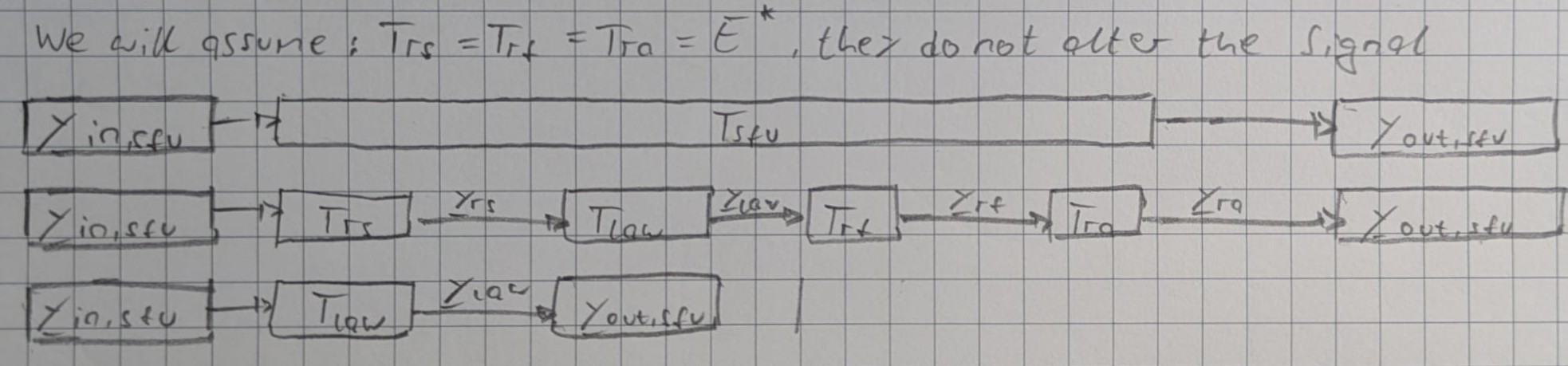
With the simplification above, the overall signal transfer function becomes:
$$T_{sfu} = T_{ra} \circ T_{rf} \circ T_{law}(s_{mode}) \circ T_{rs}(\underline{y}_{in, sfu})$$
$$T_{sfu} = T_{law}(s_{mode}, \underline{y}_{in, sfu})$$
How do we find $Z_{law}$?
The following can usually be easily obtained:
- $E^*_{sfu}$
- $Z^*_{law}$
(Slide 24 diagram will be given in exam, but we need to know how to work with it)
Signals:
$$\underline{y}{sfu} = T{law}(s_{mode.law},\underline{y}_{in-sft})$$
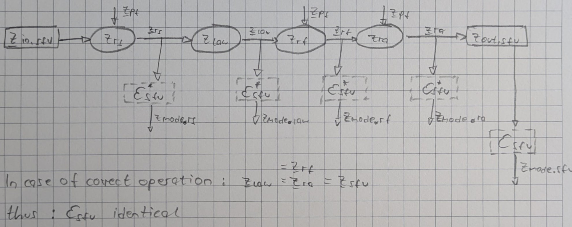
States: (correct order of the function is important)
$$\underline{z}{sfu} = {z}{sfu}(\underline{z}{pf}, \underline{z}{in.sft})$$
$$\underline{z}{sfu} = {z}{ra}(\underline{z}{pf}) \circ {z}{rf}(\underline{z}{pf}) \circ {z}^*{law}(z_{mode.law}) \circ {z}{rs}(\underline{z}{pf}, \underline{z}_{in.sfu})$$
Evaluation:
$$\varepsilon^*{sfu} = \varepsilon{sfu} \circ z_{law}$$
These functions can be used to decribe the whole system
- which inputs lead to which outputs
- system failures
- when does my system degrade to a specific mode?
How to use this information
$P(lossOfNormalLaw) = 10^{-4}$
$P(lossOfNormalLaw, alternateLaw) = 10^{-7}$
$P(lossOfNormalLaw, alternateLaw, directLaw) = 10^{-9}$
Using transfer functions, these laws can be expressed formally (see slide 27)
Creating the system requirements document YRD
To create the YRD, we need to:
- systematically find requirements for the system function
- formally define the requirements
To achieve this, we follow this process:
- develop the architecture
- develop degredation modes
- develop signals for each degredation mode
- develop functional requirements
- develop platform-dependent state transfer, evaluation functions
- allocate safety requirements
The resulting requirements form the YRD
basic arcitecture: what does the system do comprises of what each component does ($T_{sfu}$)\
Platform architecture (longest chapter in this course)
Generic state transfer functions for modules
Module A module refers ro any single or redundant hardware unit examples: signle sensor number 1 or type stick, redundant computer, single actuator elevator left hand
each module performs a state transfer function
-
- each module has a state $z_{mod}$
-
- the output states depend on:
- the input states $\underline{z}_{in}$
- the module's state $z_{mod}$
-
- the output state is correct if:
- the input states are correct
- the modules state is correct
passivating a lane can be complicated, in this lecture, we simplify these cases by considering passive lanes to have no effect on the rest of the system